Air flow detection is often necessary in many applications or systems where it is necessary to detect the presence of air to have a descriptive picture of the proper functioning of the systems. For example, we need air flow detection in engines to get an estimate about the amount of fuel to be added to the engine, we need air flow detection to check the amount of contamination or the transfer of contamination using chemical media like air. For high power density electronic devices, we need air flow detection to ensure the devices from getting over heated.
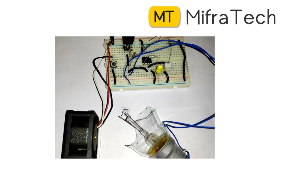
Here, a simple air flow detector circuit is developed which uses a resistance temperature detector as the basic component. This circuit is based on two principles – a) Variation of resistance with temperature, b) Air as an insulator. As current flows through the resistor, it gets heated up. Now when air is made to flow through the RTD, it being an insulator, allows the resistor to cool down. Thus resistance starts decreasing and the voltage across the RTD decreases. This variation in voltage drop is detected using a timer circuit to give an indication of the air flow.
This circuit is operated using a 12V battery. The battery voltage is regulated using the Zener diode, which produces a constant voltage. Initially as current flows through the RTD, it gets heated up and its temperature increases, thereby increasing its resistance. Now as current is constant, the voltage across the resistance also tends to increase. When this voltage is applied to the trigger pin of the timer, it fails to trigger the timer and the LED is in off condition. Now as air flows over the RTD, it starts cooling. This reduces the temperature of the device. As the temperature reduces, the resistance also reduces and so does the voltage across the device. As this voltage reduces below a certain point, the timer gets triggered and the LED starts blinking. As voltage falls further, indicating fall of temperature, the LED starts glowing with full intensity. This indicates the flow the air.
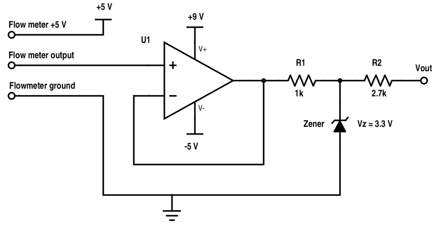
The basic theory behind this circuit involves knowledge about three basic parts- Voltage Regulator using Zener Diode, Resistance Temperature detector and a timer circuit.
This circuit can be used to detect the flow of air in areas like car engine, where it is required to estimate the amount of fuel needed by the engine. Apart from being used as an air flow detector, this circuit can also find its application as a temperature detector circuit. With slight modifications, this circuit can be used to control loads like a fan, based on temperature sensing.