Abstract
We live in a world which is moving at such a fast pace that everything if automated will help us to keep our lives going. The quest to save electrical and water resources, we developed an automatic water level controller with pump switching system for both overhead and underground tanks. This module monitors and displays level of water in a tank. When water is at the specified lowest level, pump is automatically turned ON to refill until the tank is filled to its maximum capacity, then pump is turned OFF thereby saving both inadequate electrical and water resources. The design consist of Power supply, Arduino microcontroller, Ultrasonic sensors, display and pump units. The project on water level Indicator will help us to know when the water in our tanks is either full or empty and automatically switch ON and OFF the pump as and when necessary. By using the basic principle of ultrasonic sensors, i.e the ECHO method. The 20 kHz ultrasonic distance sensor, remotely senses level of water by measuring length of emptiness or fullness of the tank from recorded time of arrival of echo from water surface. This length is interpreted and displayed by program based microprocessor in percentage of the capacity on Liquid Crystal Display (LCD) unit. The project can be extended by interfacing ESP8266 with Arduino to fetch real time status of tanks from remote location. Keywords: water monitoring, water controlling, Arduino, ultrasonic sensor, motor.
Introduction
In accordance with the current scenario, a lot of water is wasted every day from residential areas, offices and hospitals. Water is essential in various ways and such a huge amount of water wastage can lead to its scarcity in future. It is possible to achieve the level of water monitoring in a number of highways, which require many equipment, but in the system used in this paper is explained a simple system of control depends on the tools available and cheap, including sensors and ultrasonic sensor to monitor the water level in the tank Water-level ultrasonic and water level recording on the LCD screen to monitor the water level and use Bluetooth to send information about the water level of the screen by mobile phone, but the use of Bluetooth to monitor a certain distance commensurate with the extent of the Bluetooth broadcast . It is also possible to control the filling of the tank when the water is connected to the access and stop the flow of water in the tank when it reaches the full extent specified by connecting the water supply and sensor and the screen of the plug and the Bluetooth chip by Arduino, which is fed information about the water level required in the reservoir in terms of fullness The library has been written in c language for each electronic part of the parts associated with Arduino to organize the work between the parts and achieve the desired goal of intelligent reservoir management and knowledge of water level in the reservoir and the optimal use of water and non-waste.
Problem statement
It is very essential for people to have a smart solution to unnecessary electricity bills and wastage of water. In a country where average income is $1,513 a year people need a device that could automatically save their money. It is one of our sole duty to use our resources sustainably so that the generations to come could be in ease. Wastage of water is becoming common nowadays and one of the biggest reason is the overflowing of water from overhead tanks.
Literature survey
This research paper by Ria Sood, Manjit Kaur, Hemant Lenka emphases on the need of water level controller in irrigation in agriculture. It says that every crop requires require different amount of water and this can be done by using automatic water level controller which will also help in reducing wastage of water. Here they use a technique to measure flow of rate of water in irrigation pipelines. It uses a Hall Effect Sensor to measure the rate flow. G1/2 Hall Effect water flow sensor is used as a sensing unit with a turbine rotor inside it whose speed of rotation changes with the different rate of flow of water. [2] This research paper by Sanam Pudasaini, Anuj Pathak, Sukirti Dhakal, Milan Paudel presents a system of an automatic water level controller with SMS notification. SMS notification was added to automatic controller system so that water can be managed by user during load shedding. Two systems work synergistically; automatic level controller system and SMS system. The program was developed in Arduino program developing environment and uploaded to the Microcontroller. Water level in the system is controlled automatically. The controller operates on a battery power. Whenever the system encounters empty level and the status of load shedding, the SMS notification is sent to the user. The system will automate the process by placing a single sensor unit in the tank that will periodically take measurements of the water level and will control the motor automatically. This system eliminates the efforts of people for daily filling of the tank and checks for overflow. [3] This research paper by Asaad Ahmed Mohammedahmed Eltaieb , Zhang Jian Min involves designing and development of automatic water level control system had exposed to the better way of software and hardware architecture that blends together for the interfacing purposes. The system employs the use of advance sensing technology to detect the water level. It uses Arduino and uses relay to control motor. Different wires are attached at different Junctions of the Beaker. When we pour water in the beaker. The water comes in contact with the wire and tells the level of water in the tank. Accordingly, they have displayed the level of water on LCD display. And uses relay to turn ON and OFF the motor.
Objective
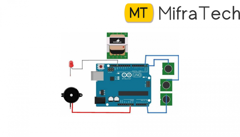
To develop a water proof, low cost water monitoring and controlling module which saves wastage of water from overhead tanks and avoids dry running of motor in case non availability of water in sump tank.The above figure 1 represents the block diagram of the proposed concept. Once the module is powered up, the ultrasonic sensor propagates an echo signal which is measured by the Arduino and hence the level of the water within the tank in computed using Echo method. In Echo method Arduino reads the time between triggering and received ECHO. The speed of sound is around 340 m/s. Hence distance is calculated using the formula: Distance= (travel time/2) * speed of sound Where; Speed of sound is approximately 340m per second. By using this method we compute distance from sensor to water surface. Later the same information is computed as percentage of water available in sump and overhead tank. If the level of the water within the tank is less than the threshold value programmed then motor will be driven by the controller via motor driver circuit, however if the level of water in the tank is greater than the threshold value programmed then the motor will be in the OFF state. The level of water is continuously monitored and is displayed on the LCD. The motor will not turn On if sump water level is below threshold to protect the motor from dry running. Before switching ON and OFF the motor the user is been indicated by different tones of the buzzer.
Hardware implementation
The hardware design of the overall system has been implemented in the same form as it was designed. The subsystems implemented are illustrated in a sequence. As shown in the above Fig. 2, the 230V AC 50 Hz supply is given to step down center tapped transformer (15-0-15) V, 1A. Here the voltage is stepped down from 230V to (15-0-15) V then by using two diode full wave rectification circuit the voltage is rectified and converted into pulsating dc that is fed to capacitive filter to remove the ripple content from the voltage and then it is fed to 7815 regulator IC to get a regulated power supply of 15V DC, 1A. Appropriate heat sink is included to dissipate the heat developed during the operation. The same is used to drive Arduino, sump motor and various others components in the circuit.The ultrasonic sensor has four pins Vcc, GND, ECHO and Trig. The Vcc and GND pins of ultrasonic sensor is connected to Vcc & GND pins of Arduino. The trigger and echo pins are interfaced to any GPIO pins of Arduino. In order to generate the ultrasound signal the trigger pin is set on a High State for 10 µs. That will send out an 8 cycle sonic burst which will travel at the speed sound and it will be received in the Echo pin. The Echo pin will output the time in microseconds the sound wave traveled. For example, if the object is 10 cm away from the sensor, and the speed of the sound is 340 m/s or 0.034 cm/µs the sound wave will need to travel about 294 u seconds. But data at Echo pin will be double that number because the soundwave needs to travel forward and bounce backward. So in order to get the distance in cm we need to multiply the received travel time value from the echo pin by 0.034 and divide it by 2. The same can be monitored at serial monitor of Arduino software.
Result
s With several iterations performed it was found that, when the sump tank has the water level below than the (20%) threshold then motor was in the OFF state to avoid dry run condition. If the water in the overhead tank falls below 10% and availability of water in the sump tank is greater than 20% then motor goes to ON state. The instant when water level in the overhead tank reaches 100% the motor goes to OFF state. The following is truth table which is verified by performing several iterations on the module.
Conclusion
Based on the results it can be stated that automatic water level in sump tank and overhead tank is implemented which saves water wastage and supports in conservation of water and electricity.
Future scope
The project could be extended by installing pH sensors which will help to regulate the acidity or alkalinity of the water. Hence providing the information for need of cleaning the tank. The same implemented system could be monitored using an app operating on IoT. Use this template to prepare the manuscript easily. The next section shows how to cite the references.
embeeded and electronics projects
embedded electronics projects
embedded systems final year projects
embedded based final year projects
embedded related projects
embedded project
embedded projects for ece
embedded system projects for ece
embedded systems mini projects for ece
embedded based projects for ece
embedded systems projects for eee
embedded project ideas
embedded systems final year project ideas
embedded system based final year projects
embedded project topics
embedded final year projects for ece
best ai projects for beginners
https://www.mifratech.com/public/
https://www.facebook.com/mifratech.lab
https://www.instagram.com/mifratech/
https://twitter.com/mifratech