In this project, I will show you how to design a simple Battery Level Indicator Circuit using easily available components. Battery level indicator indicates the status of the battery just by glowing LED’s. For example six LED’s are glowing means battery capacity 60% remains.
This article explains you how design battery level indicator. You can use this circuit to check car battery or inverter. So by using this circuit, we can increase the lifetime of battery.

This circuit is designed based on lM3914 IC (Integrated chip). This IC is LED dot/bar display driver.
The heart of this battery level indicator circuit is LM3914 IC. This IC takes input analog voltage and drives 10 LED’s linearly according to the input analog voltage. In this circuit, there is no need of resistors in series with LEDs because the current is regulated by the IC.
In this circuit LED’s (D1-D10) displays the capacity of the battery in either dot mode or display mode. This mode is selected by the external switch sw1 which is connected to 9th pin of IC. 6th and 7th pins of IC are connected to the ground through a resistor. This resistor controls the brightness of LED’s. Here resistor R3 and POT RV1 forms potential divider circuit. Here pot RV1 is used for calibration. There is no need of any external power supply to this circuit.
The circuit is designed to monitor 10V to 15V DC. The circuit will work even if the battery voltage is 3V. The operating voltage of this IC is 3v to 25v DC. Lm3914 drives led’s, LCDs and vacuum fluorescents. The IC contains adjustable reference and accurate 10-steps divider. This IC can also acts as sequencer.
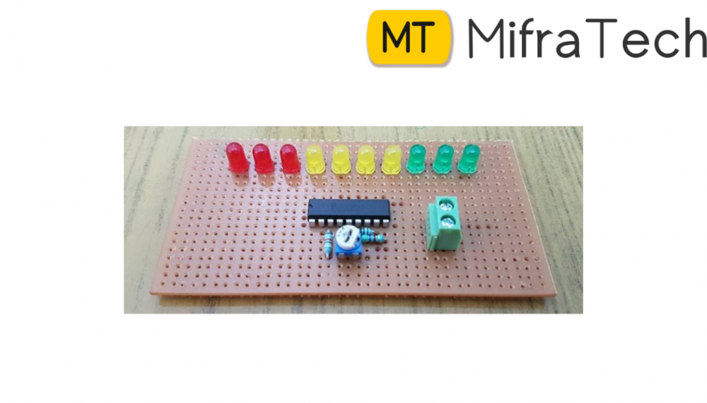
We can also connect different color led’s to indicate the status. Connect D1 to D3 red LED’s which indicates shut down stage of your battery and use D8-D10 green color LED’s which indicates 80 to 100 percentage of the battery and use yellow color for remaining.