FM Radio circuit is the simple circuit that can be tuned to the required frequency locally. This article describes the circuit of FM radio circuit. This is a pocket sized radio circuit.
Radio is the reception of electromagnetic wave through air. The main principle of this circuit is to tune the circuit to the nearest frequency using the tank circuit. Data to be transmitted is frequency modulated at the transmission and is demodulated at the receiver side
Circuit Components
The FM Radio circuit mainly consists of LM386 IC. This is a low voltage audio power amplifier. It has 8 pins. It operates at a supply voltage of 4-12 volts. It has an op-amp internally, which acts as an amplifier. The non-inverting pin is connected to the variable resistor of 10KOhms. Inverting pin of the LM386 IC is connected to the ground. Sixth pin is connected to the VCC. Fourth pin is connected to the ground. Fifth pin is output and is connected to the capacitor which is connected to the speaker or microphone. Another capacitor is connected to ground pin. Sixth pin is the supply pin connected to the supply voltage. This amplifies the incoming frequency modulated signal.
BF494 is an NPN RF transistor. Initially it is open circuited. It starts conducting only when base gets the required cut off voltage. Base of the transistor is connected to the base of the variable resistor through a capacitor of 0.22uF. Emitter pin is connected to the ground. Collector is connected to the tank circuit. Base of transistor Q2 is connected to the tank circuit. Emitter pin is connected to the ground and collector is connected to the supply through a resistor of 22K ohms. The variable resistor controls the volume to the input amplifier. These transistors are used for detecting the frequency modulated signals.
Output of the IC is connected to the headphones or Mylar speaker through a capacitor of 220uf 25v rated. The head phone or speaker will have two wires out. One is connected to the output of the capacitor and the other pin is connected to the ground pin.
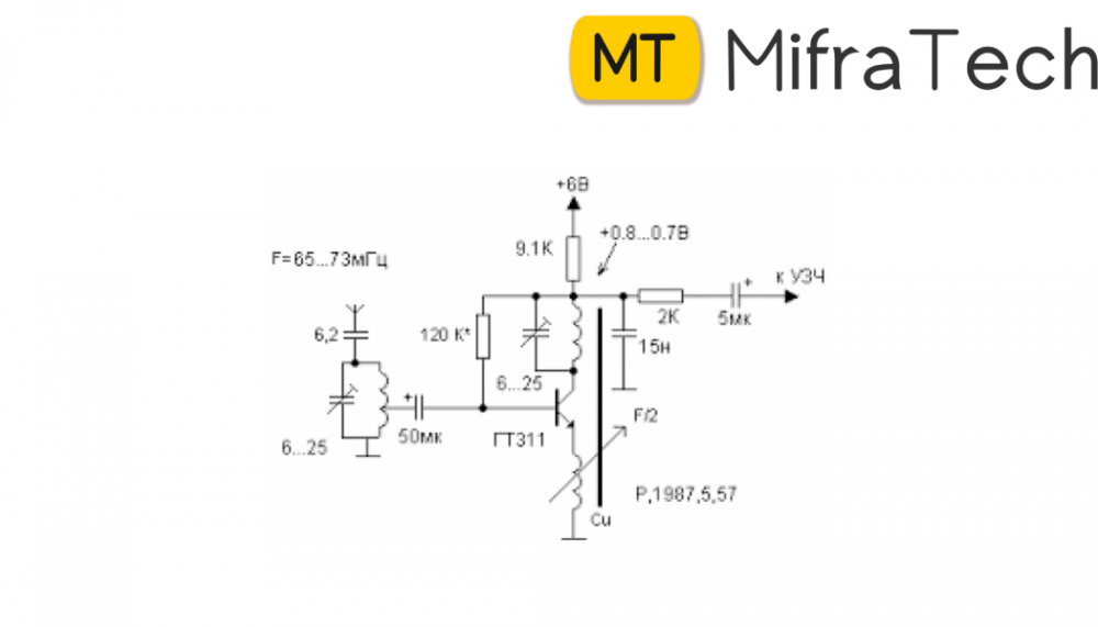
Tank circuit consists of a coil and a variable capacitor .This is connected to the antenna. This is the main part of the circuit as it tunes the radio to the required local frequency. In this tank circuit coil plays a main role. Coil is a copper wire wind into fixed number of turns.
To operate the FM Radio circuit following steps are to be followed: