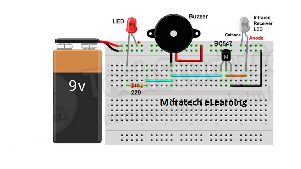
In this project, we will make a simple fire detector alarm circuit using BC547 transistor and IR detector LED on Breadboard. This circuit can easily detect any fire nearby and accordingly start the buzzer.
Circuit diagram of fire detector

Components required
1. BC547 Transistor (NPN) 1no
2. Infrared Receiver LED 1no
3. 220-ohm Resistor 1no
4. LED 5mm 1no
5. DC Buzzer 1no
6. 5 volt DC supply or 9 Volt Battery.
7. Breadboard
In this fire alarm circuit, we have used an infrared detector LED. The infrared emitted from the fire is detected by the infrared LED and voltage across the infrared led changed. The Anode of the infrared LED is connected with the base of the BC547 NPN transistor. Due to the positive pulse in the base, the transistor turns on and current can flow in through buzzer –> Collector –> Emitter.
If there is no fire then no positive pulse fed to the transistor base so the BC547 transistor remains in off mode. So that time current can not flow through the buzzer
refer our youtube videos, please like and subscribe our yotube channel
Mifratech eLearning : https://www.youtube.com/channel/UCVBnP3kN_dRKa4gXzrfBcqQ