In this project, we will see a PWM based LED Dimmer using 555 Timer IC. The main principle of this circuit is to generate a Pulse Width Modulation PWM Signal with the help of the good old reliable 555 Timer IC and vary the power being delivered to the LEDs and hence achieving the effect of LED Dimming.
The Pulse Width Modulation (PWM) plays an important role in controlling the a lot of circuits. If you want to control the speed of the motor, PWM plays a key role. Here, in our project, the PWM Technique is used for dimming the LEDs.
The 555 Timer is an 8-pin Integrated Circuit available in Dual-in-Line Package originally developed by Signetics. It is one of the most popular ICs and is used for a variety of applications like Timer, Oscillator and Pulse Generation.
Pin Diagram of the 555 Timer IC is shown in the following image. The pin 8, which is the VCC pin, is used to give the main supply voltage to the IC. The operating voltage may vary from 3v to 15V. Pins 2, 6 and 7 are the Trigger, Threshold and the Discharge Pins.
Pin 4 is the Reset pin and it is used to reset the complete IC. It is an active LOW Pin. The output of the IC can be taken from the out pin i.e. the pin 3. Pin 5 is the Control Pin.
The 555 Timer IC can work in three different modes of operation: Astable, Monostable and Bistable operations. It has features like timing for micro seconds through hours, adjustable duty cycles and ability work in various voltage levels etc. It has a wide range of applications like lamp dimmers, motor control, joysticks etc.
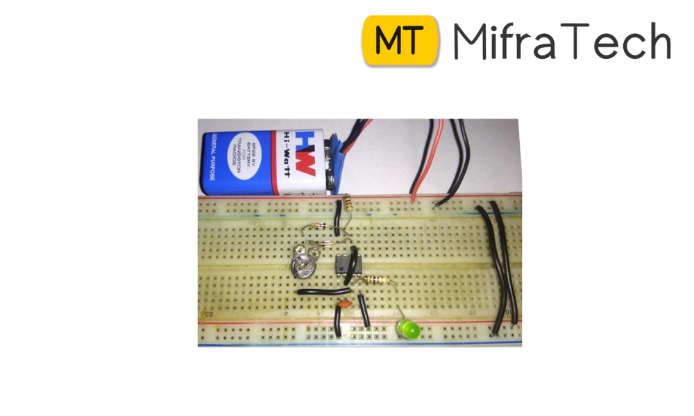
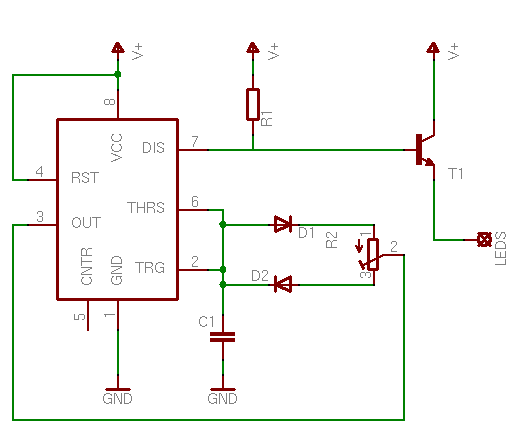
Here in this project, the 555 Timer is made to operate in the Astable Multivibrator Mode. The 1KΩ Resistor, the 50KΩ POT and the 0.1μF Capacitor connected with respect to Pins 2, 6 and 7 will play an important role.
Based on the charge and discharge timings of the Capacitor, a PWM Signal is generated at the OUT Pin i.e. Pin 3 of the 555 Timer IC. The output of the 555, which is taken form pin 3, is connected to the led panel through the NPN Transistor (2N2222 is used here) and a 1KΩ resistor.