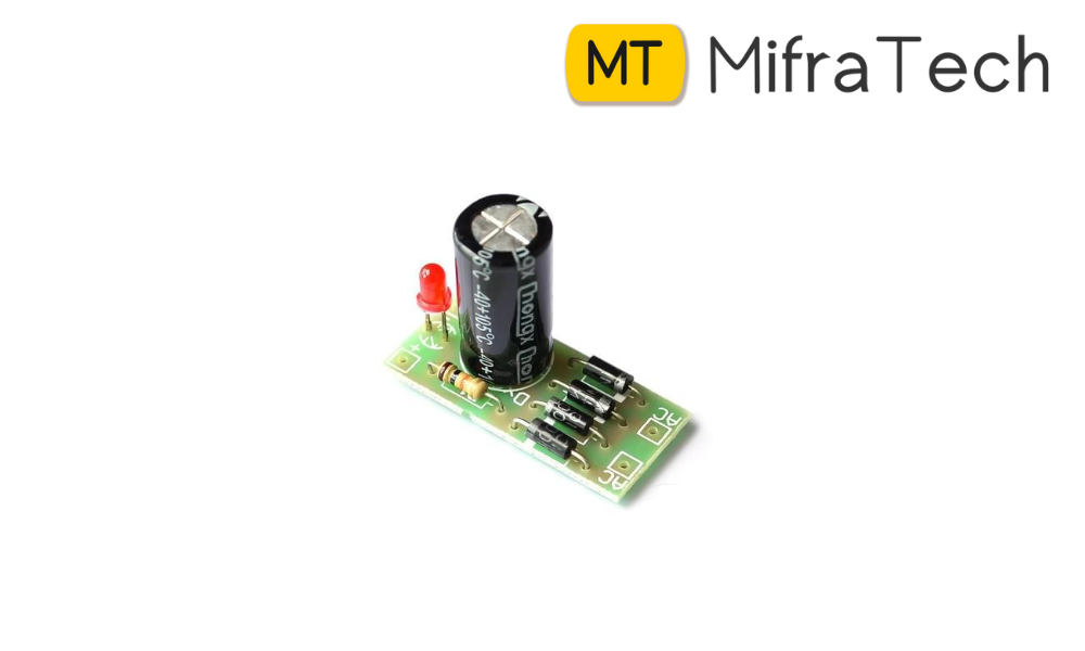
An AC power source is required for powering major appliances but almost all electronic circuits require a steady DC supply. A simple rectifier circuit described in this project converts the input from AC source to DC voltage. Firstly, the AC input from mains is stepped down to a lower value of voltage. This AC supply is then passed through a rectifier circuit to remove the negative cycle of AC waveform. The resulting signal is then filtered to get the DC output. The major part of the circuit is connected to the secondary coil of the transformer which is comprised by diodes and capacitor. While the diodes act as actifiers, capacitor filters out the DC component from the circuit.
In this project, the input mains supply is stepped down from 230 V AC to a desired level (depending upon the rating of the load connected). Peak voltage across the load is matched to the peak value of AC voltage from output of a transformer. This is achieved here by using a step down transformer 12-0-12V of 500mA rating. The reduced voltage level (12V) appears on the secondary winding of the transformer. This AC signal has alternating positive and negative waveform cycle while the desired output should always be positive. Therefore the signal is rectified using a bridge rectifier to block the negative portion of the waveform. Almost all rectifiers comprise a number of diodes in a certain arrangement for converting AC to DC than is possible with only one diode. Here, four 1N4007 diodes (D1-D4) have been used as shown in the circuit diagram. The bridge rectifier rectifies the stepped down AC to pulsating DC which contains ripples. So a filter capacitor C1(1uF) is connected across the output of the rectifier so as to bypass the AC component present in it. The output obtained can now be used to power electronic devices/circuits.