Water Sensor Circuit
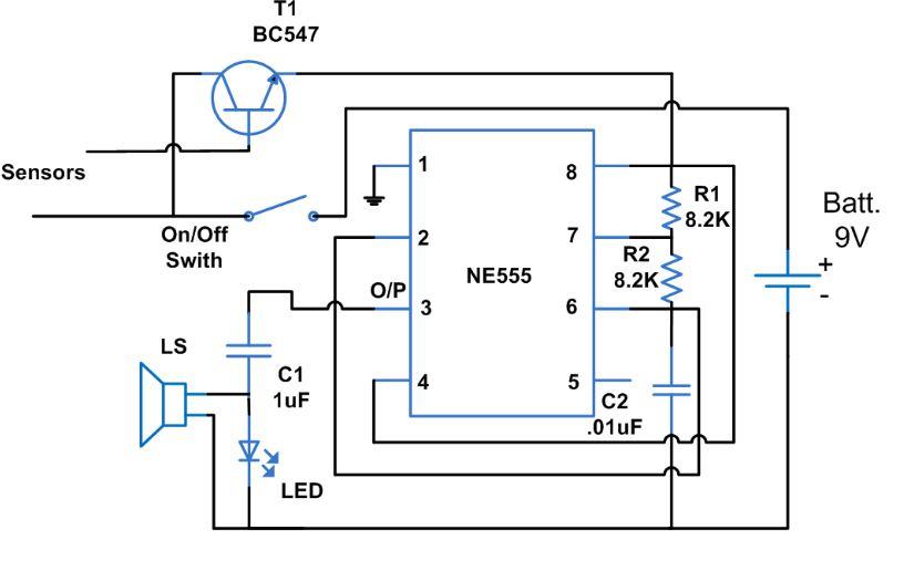
In this water sensor circuit based project, 555 timer works in astable mode. It is driven by the emitter current which is coming from BC548 transistor as this transistor has high gain. In astable mode IC 555 functions as an oscillator. So for 555 to work in full oscillator mode a high current is required so as to trigger it. As the probes sense the moisture on it, the transistor gets switched ON and small current starts flowing between the base and the emitter. When no moisture is detected i.e. in dry state it remains OFF.
Initially as the supply is switched ON, the voltage at output pin of 555 timer is 0V. At this stage transistor will not conduct as the emitter current is LOW. Pin8 i.e. Vcc of 555 timer is connected to the collector of the transistor. As the transistor is switched OFF there will be no supply to 555 timer. As the water is sensed at the probes, transistor gets into its saturation region and starts conducting. As a result 555 gets supply for its operation. Its operation starts very soon as it is in astable mode. Sound is produced because of output pulses at pin3 which drives the loud speaker.
An ON/OFF state switch is used to control the conduction. The probes should be made up of non reactive metal so that there will be no inductance or capacitance present. An alternative can also be there i.e. use of alternate copper wires. No base resistor is required in this circuit because the transistor is in switch mode. The impedance at the emitter or the oscillator circuit acts as current limit.