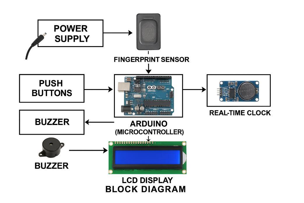
The Fingerprint-Based Attendance System is a biometric authentication project that automates and secures attendance tracking using a fingerprint sensor and microcontroller. This system eliminates the need for manual or card-based attendance, reducing the chances of proxy marking and ensuring reliable identification. Each user’s fingerprint is registered and matched during attendance logging. The real-time clock (RTC) module timestamps each record, and an LCD display provides feedback to the user. It is ideal for schools, colleges, offices, and secure facilities, where accurate and tamper-proof attendance is critical.
Arduino UNO:
The Arduino UNO acts as the central microcontroller. It handles all operations — such as fingerprint matching, data processing, communication with peripherals (LCD, fingerprint sensor, RTC), and controlling output components like the buzzer and LEDs. It runs the program logic written in Arduino C/C++.
🔸 Fingerprint Sensor (R305/R307):
This is the core biometric device used to capture, process, and store fingerprints. When a user places their finger on the sensor:
-
It scans the fingerprint,
-
Matches it with stored templates (if any),
-
Sends success or failure feedback to the Arduino.
It supports two operations:
-
Enrollment – Stores a new fingerprint template.
-
Matching – Compares scanned fingerprint with saved templates.
🔸 Real-Time Clock (RTC - DS3231/DS1307):
The RTC module is used to track the exact date and time when attendance is recorded. Even if the Arduino is turned off, the RTC keeps time using a coin-cell battery. This ensures timestamped attendance logs, which are essential for tracking punctuality and creating reports.
🔸 16x2 LCD Display:
This alphanumeric display is used to provide real-time feedback to the user. It displays:
-
System status (e.g., "Place Finger", "Access Granted", "Try Again"),
-
Attendance confirmation with timestamp,
-
Menu options for enrolling or deleting fingerprints.
🔸 Push Buttons:
Used to navigate between system functions such as:
-
Enroll new fingerprint
-
Delete fingerprint
-
View system status
-
Reset system
Each button can trigger a specific mode, making the system interactive and flexible.
🔸 Buzzer:
Provides audio feedback. A short beep indicates successful scanning, while a long or multiple beeps may indicate errors or failure. This enhances user experience by giving immediate feedback.
🔸 LED Indicator:
Used as a visual status indicator:
This improves accessibility and gives quick insight into system activity.
🔸 Breadboard and Jumper Wires:
Used to create a temporary prototype circuit for testing and development. All connections between Arduino and components are made via jumper wires on a breadboard.

The Images used are for sample purposes only.

.svg)