Introduction
The Arduino-Based Self-Balancing Robot System with Bluetooth Module is a two-wheeled robot designed to maintain its balance using real-time sensor feedback and closed-loop control. What makes this system advanced is the integration of a Bluetooth module that enables wireless communication for remote monitoring and control using a smartphone or computer.
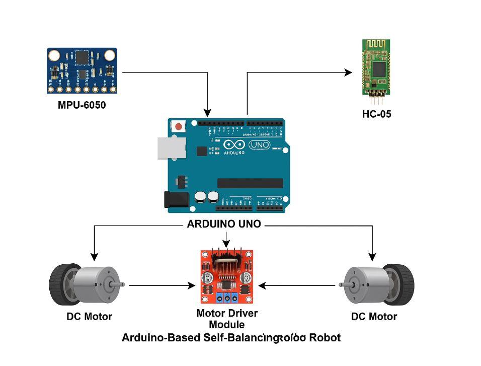
This robot simulates the concept of an inverted pendulum, a classic problem in control theory. It uses an MPU-6050 sensor (gyroscope + accelerometer) to measure tilt, an Arduino Uno for processing sensor data and executing control algorithms (like PID), and a motor driver to control two DC motors. The Bluetooth module (HC-05) allows for remote data visualization, system tuning, or manual override of movement via a mobile app or terminal interface.
Working Principle
The self-balancing robot uses real-time feedback to maintain an upright position:
-
The MPU-6050 sensor continuously measures angular velocity and acceleration.
-
This data is sent to the Arduino Uno, which calculates the current tilt angle using sensor fusion techniques.
-
The PID controller in the Arduino determines the appropriate motor speed and direction to correct the tilt.
-
The motor driver module controls the DC motors, which move forward or backward to restore balance.
-
The Bluetooth module (HC-05) allows wireless transmission of data like tilt angle, motor speed, or PID values and also enables remote control commands from a mobile device.
-
The loop continues in real time, achieving stable self-balancing while enabling wireless control.
Methodology
1. Sensor Integration
2. Control Algorithm
-
The filtered angle is passed into a PID control loop running on the Arduino Uno.
-
The PID controller calculates the necessary correction based on proportional, integral, and derivative components of the error.
3. Motor Control
4. Bluetooth Communication
-
An HC-05 Bluetooth module is connected to the Arduino’s serial pins.
-
It sends telemetry data (e.g., current tilt angle, motor output) to a mobile app or terminal.
-
It can also receive commands for manual tuning, start/stop, or remote control.
Components Used
| Component |
Function |
| Arduino Uno |
Core microcontroller that processes sensor data and controls motors. |
| MPU-6050 |
6-axis sensor (accelerometer + gyroscope) to detect tilt and motion. |
| Motor Driver Module (L298N / L293D) |
Controls the direction and speed of the DC motors. |
| DC Motors (2) |
Provide drive force and balance correction through wheel motion. |
| HC-05 Bluetooth Module |
Enables wireless communication for data monitoring and control. |
| Power Supply |
Provides voltage to power the Arduino and motor driver. |
| Wheels and Chassis |
Structural base of the robot. |
| Jumper Wires & Breadboard |
Circuit prototyping and connections. |
Block Diagram:

IMAGES USED ARE ONLY FOR SAMPLE PURPOSES !!!!!!!

.svg)