Introduction
Traffic congestion is a growing issue in urban areas, often caused by poorly timed or manually operated traffic lights. The Arduino-Based Traffic Configuration System is designed to offer an automated and programmable solution to manage traffic flow efficiently. By using an Arduino Uno microcontroller and basic electronic components like LEDs and timers, the system simulates or controls traffic lights in a preconfigured or sensor-based sequence. This project can be used in both educational simulations and practical traffic signal control scenarios.
This system is low-cost, easy to build, and highly customizable. It allows traffic lights to operate in a sequence with programmed timing, mimicking real-world junction behavior. It can also be extended to include real-time traffic density sensing using IR or ultrasonic sensors.
Working Principle
The system is programmed with a predefined timing logic that simulates a four-way traffic signal system:
-
The Arduino Uno is programmed to manage the sequence and duration of traffic signals (Red, Yellow, Green).
-
LEDs represent the traffic lights for each direction.
-
Each signal turns ON/OFF based on a fixed time interval set in the Arduino sketch.
-
Timers and delays manage signal transitions to avoid conflicting green lights at intersecting paths.
-
The system loops this sequence continuously, simulating a real-world traffic control system.
This system can be expanded to include sensors, but in its base form, it works purely on timing logic.
Methodology
The methodology for the Arduino-Based Traffic Configuration System follows a step-by-step logic design:
1. Design of Traffic Signal Logic
-
Each direction is given Green, Yellow, and Red signals in sequence.
-
Each signal phase is assigned a fixed delay (e.g., Green = 10s, Yellow = 3s, Red = remaining time).
2. Arduino Programming
3. Signal Loop Execution
-
After executing the complete cycle for all four directions, the loop restarts.
-
The sequence ensures no two adjacent directions have green signals simultaneously.
4. Circuit Construction
-
LEDs representing signals are connected to digital I/O pins.
-
Resistors are used to limit current to the LEDs.
-
Power is supplied via USB or battery to the Arduino.
Components Used
| Component |
Function |
| Arduino Uno |
Acts as the brain of the system, controlling timing and signal logic. |
| LEDs (Red, Yellow, Green) |
Represent traffic lights for each direction. |
| Resistors (220Ω) |
Current limiting resistors for LEDs. |
| Jumper Wires |
For circuit connections between the Arduino and LEDs. |
| Breadboard |
Used for prototyping and assembling components. |
| Power Supply (USB or Battery) |
Powers the Arduino and components. |
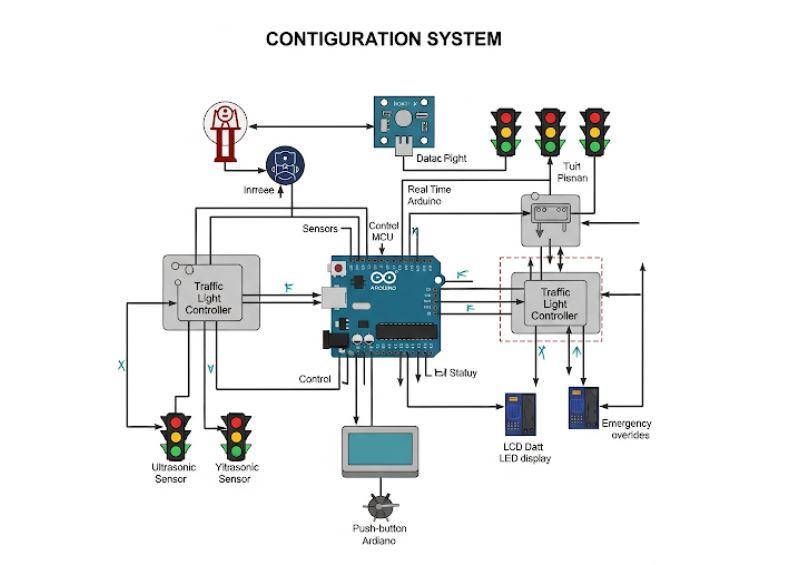
Block Diagram:

IMAGES USED ARE ONLY FOR SAMPLE PURPOSES!!!!!!

.svg)