Introduction:
The Smart Battery Management System (SBMS) is an advanced electronic control system designed to monitor and manage the performance, health, and safety of battery packs. It plays a critical role in systems like electric vehicles, solar power setups, UPS systems, and other energy storage applications where battery efficiency and safety are crucial.
The SBMS continuously measures parameters such as voltage, current, temperature, and state of charge (SoC) of the battery. Based on this data, it controls the charging and discharging cycles to prevent overcharging, deep discharge, overheating, and imbalance among battery cells. By providing real-time data and intelligent decision-making, the SBMS ensures maximum battery life, efficient energy usage, and safe operation.
Working Principle:
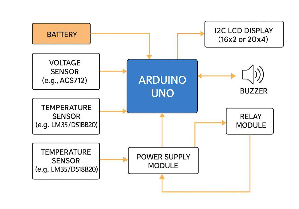
The Smart Battery Management System works by using sensors and microcontrollers to constantly monitor various parameters of the battery:
-
Voltage Sensor measures the terminal voltage of the battery.
-
Current Sensor measures the current flowing in and out of the battery.
-
Temperature Sensor monitors the thermal conditions of the battery to prevent overheating.
-
The microcontroller processes these values and determines the battery's health, SoC, and SoH (State of Health).
-
Based on predefined thresholds, the system activates or deactivates relays to control charging or discharging devices (e.g., motors, inverters, etc.).
-
Real-time values are shown on an LCD display, and warnings (such as overvoltage or overheating) are triggered via buzzer or LEDs.
This feedback loop ensures the battery is used within safe operating conditions, increasing its reliability and lifespan.
Methodology:
-
Initialization:
The microcontroller initializes and calibrates all connected sensors and peripherals upon startup.
-
Real-Time Monitoring:
Sensors continuously send voltage, current, and temperature data to the microcontroller.
-
Data Processing:
The microcontroller calculates the State of Charge (SoC), checks for faults like overvoltage, undervoltage, or overtemperature, and logs important readings.
-
Control Actions:
Based on sensor readings, relays are triggered to cut off charging/discharging or activate cooling mechanisms (like fans or alerts).
-
User Feedback:
The system displays real-time parameters on an LCD and alerts the user with a buzzer if unsafe conditions are detected.
Components Used:
| Component |
Description |
| Arduino Uno / ESP32 |
Main microcontroller for processing sensor data and controlling relays. |
| Voltage Sensor |
Measures the battery's voltage to prevent overcharge/undercharge. |
| Current Sensor (e.g., ACS712) |
Measures the current flow to and from the battery. |
| Temperature Sensor (e.g., LM35/DS18B20) |
Monitors the battery temperature to prevent overheating. |
| Relay Module |
Used to control external loads or disconnect charging/discharging based on safety conditions. |
| I2C LCD Display (16x2 or 20x4) |
Displays real-time battery parameters. |
| Buzzer |
Alerts user during abnormal conditions. |
| Power Supply Module |
Provides stable power to the microcontroller and sensors. |
Block Diagram:

IMAGES USED ARE ONLY FOR SAMPLE PURPOSES!!!!!!

.svg)